

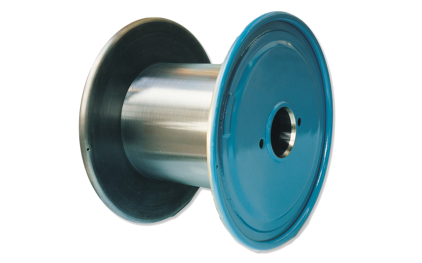
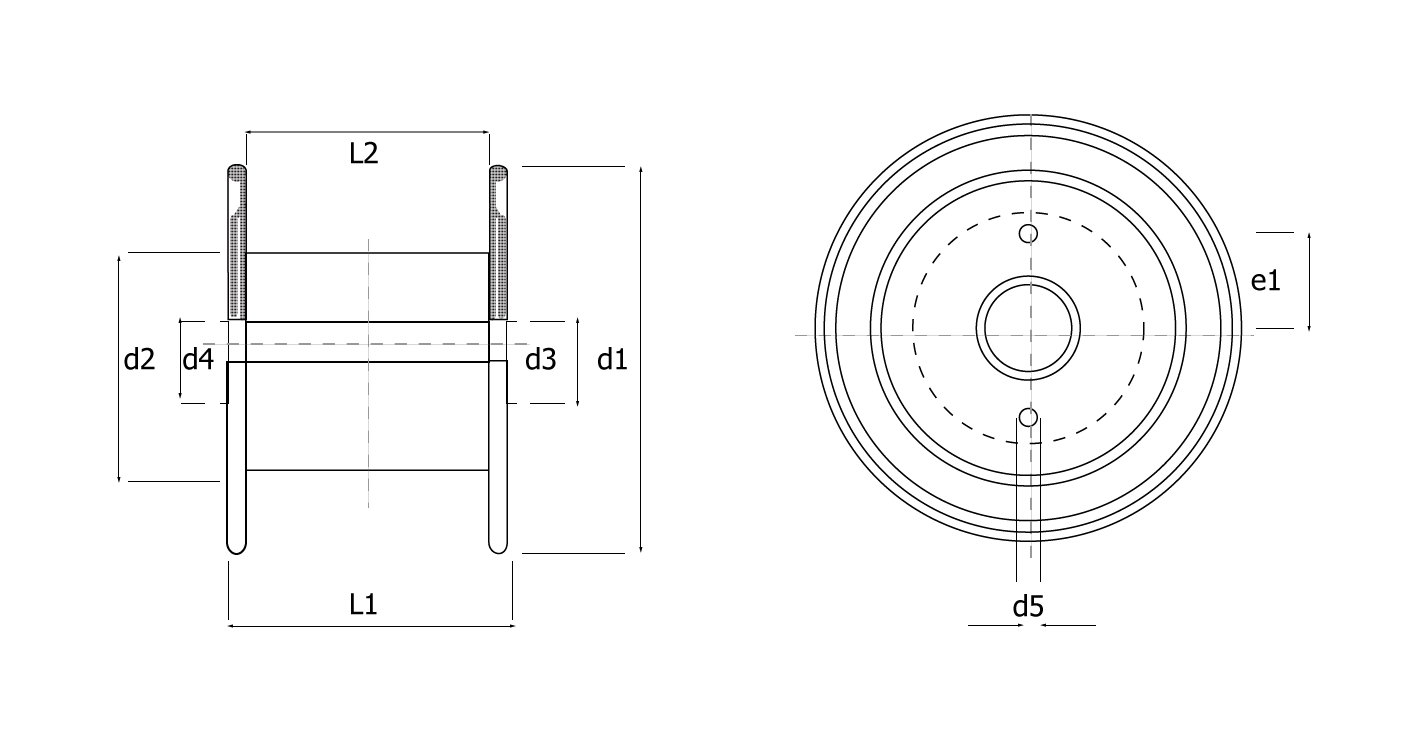
Key: d1 = flange diameter; d2 = barrel diameter; d3 = outside diameter; d4 = bore diameter; d5 = drive hole / pin diameter; e1 = drive radius; L1 = through bore; L2 = traverse.
| d1 | d2 | d3 | d4 | d5 | e1 | L1 | L2 | Vol. dm3 |
|---|---|---|---|---|---|---|---|---|
| 400 | 224 | 160 | 127 | 28 | 100 | 236 | 200 | 17.3 |
| 400 | 224 | 160 | 127 | 28 | 100 | 300 | 250 | 21.6 |
| 400 | 250 | 160 | 127 | 28 | 100 | 300 | 250 | 19.1 |
| 400 | 280 | 160 | 127 | 28 | 100 | 300 | 250 | 16.0 |
| 450 | 250 | 160 | 127 | 28 | 100 | 265 | 224 | 24.6 |
| 450 | 250 | 160 | 127 | 28 | 100 | 335 | 280 | 30.8 |
| 450 | 280 | 160 | 127 | 28 | 100 | 335 | 280 | 27.3 |
| 450 | 315 | 160 | 127 | 28 | 100 | 335 | 280 | 22.7 |
| 500 | 280 | 160 | 127 | 28 | 100 | 300 | 250 | 33.7 |
| 500 | 280 | 160 | 127 | 28 | 100 | 375 | 315 | 42.5 |
| 500 | 315 | 160 | 127 | 28 | 100 | 375 | 315 | 37.5 |
| 500 | 355 | 160 | 127 | 28 | 100 | 375 | 315 | 30.7 |
| 560 | 315 | 160 | 127 | 28 | 100 | 335 | 280 | 47.1 |
| 560 | 315 | 160 | 127 | 28 | 100 | 425 | 355 | 59.8 |
| 560 | 355 | 160 | 127 | 28 | 100 | 425 | 355 | 52.3 |
| 560 | 400 | – | 127 | 28 | 100 | 425 | 355 | 42.8 |
| 630 | 355 | 160 | 127 | 28 | 100 | 375 | 315 | 67.0 |
| 630 | 355 | 160 | 127 | 28 | 100 | 475 | 400 | 86.2 |
| 630 | 400 | 160 | 127 | 28 | 100 | 475 | 400 | 74.4 |
| 630 | 450 | 160 | 127 | 28 | 100 | 475 | 400 | 61.1 |
| 710 | 400 | 300 | 250 | 40 | 170 | 425 | 355 | 95.9 |
| 710 | 400 | 300 | 250 | 40 | 170 | 530 | 450 | 121.6 |
| 710 | 450 | 300 | 250 | 40 | 170 | 530 | 450 | 106.6 |
| 710 | 550 | 300 | 250 | 40 | 170 | 530 | 450 | 89.8 |
| 800 | 450 | 300 | 250 | 40 | 170 | 475 | 400 | 137 |
| 800 | 450 | 300 | 250 | 40 | 170 | 600 | 500 | 172 |
| 800 | 500 | 300 | 250 | 40 | 170 | 600 | 500 | 153 |
| 800 | 560 | 300 | 250 | 40 | 170 | 600 | 500 | 128 |
| 1000 | 560 | 300 | 250 | 50 | 250 | 750 | 630 | 340 |
| 1000 | 630 | 300 | 250 | 50 | 250 | 750 | 630 | 298 |
| 1000 | 710 | 300 | 250 | 50 | 250 | 750 | 630 | 245 |
| 1250 | 710 | 300 | 250 | 50 | 250 | 950 | 800 | 665 |
| 1250 | 800 | 300 | 250 | 50 | 250 | 950 | 800 | 580 |
| 1250 | 900 | 300 | 250 | 50 | 250 | 950 | 800 | 473 |
Key: d1 = flange diameter; d2 = barrel diameter; d3 = outside diameter; d4 = bore diameter; d5 = drive hole / pin diameter; e1 = drive radius; L1 = through bore; L2 = traverse.
| d1 | d2 | d3 | d4 | d5 | e1 | L1 | L2 | Vol. dm3 |
|---|---|---|---|---|---|---|---|---|
| 400 | 160 | 112 | 56 | 16 to 28 | 112 | 300 | 250 | 26.3 |
| 400 | 200 | 112 | 56 | 16 to 28 | 112 | 236 | 200 | 18.8 |
| 450 | 180 | 112 | 56 | 16 to 28 | 112 | 335 | 280 | 37.4 |
| 450 | 224 | 112 | 56 | 16 to 28 | 112 | 265 | 224 | 26.8 |
| 500 | 200 | 112 | 56 | 16 to 28 | 140 | 375 | 315 | 51.9 |
| 500 | 250 | 112 | 56 | 16 to 28 | 140 | 300 | 250 | 36.8 |
| 560 | 224 | 112 | 56 | 16 to 28 | 140 | 425 | 355 | 73.4 |
| 560 | 280 | 112 | 56 | 16 to 28 | 140 | 335 | 280 | 51.7 |
| 630 | 250 | 112 | 56 | 16 to 28 | 140 | 475 | 400 | 105.1 |
| 630 | 315 | 112 | 56 | 16 to 28 | 140 | 375 | 315 | 72.5 |
| 710 | 355 | 160 | 80 | 28 to 40 | 160 | 530 | 450 | 133.6 |
| 800 | 400 | 160 | 80 | 28 to 40 | 160 | 600 | 500 | 188.5 |
| 900 | 450 | 160 | 80 | 28 to 40 | 160 | 670 | 660 | 267.2 |
| 1000 | 500 | 160 | 80 | 28 to 40 | 160 | 750 | 630 | 371.1 |
| 1120 | 560 | 160 | 80 | 28 to 40 | 160 | 850 | 710 | 524.6 |
| 1250 | 630 | 160 | 80 | 28 to 40 | 160 | 950 | 800 | 732.4 |

