

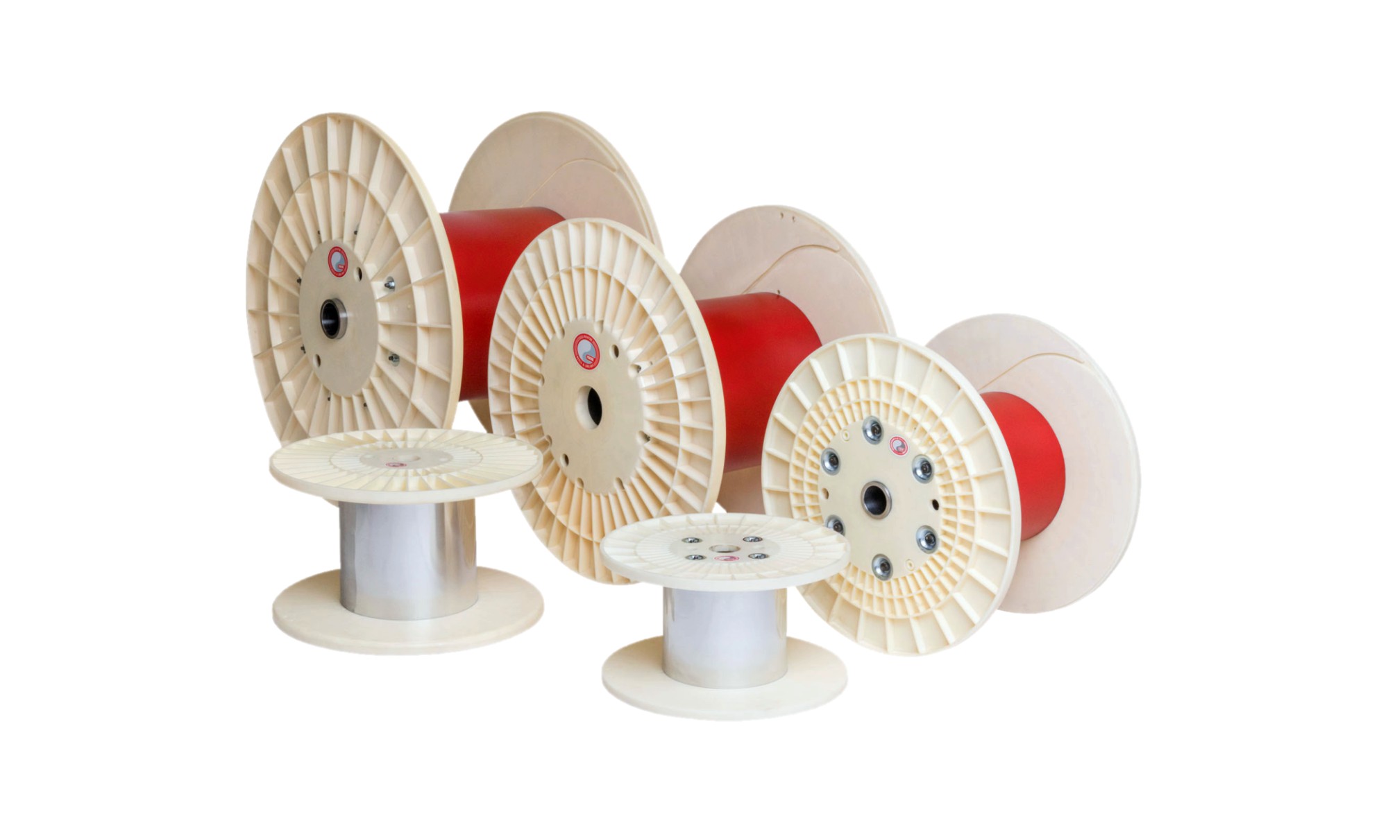
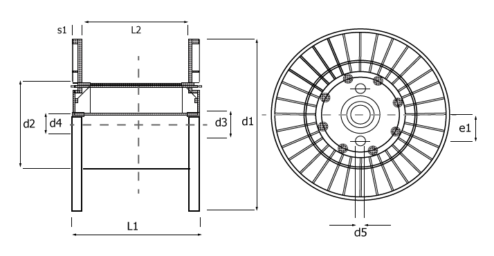
Key: d1 = flange diameter; d2 = barrel diameter; d3 = outside diameter; d4 = bore diameter; d5 = drive hole / pin diameter; e1 = drive radius; L1 = through bore; L2 = traverse.
| Product type | d1 | d2 | d3 | d4 | d5 | e1 | L1 | L2 | Vol. |
|---|---|---|---|---|---|---|---|---|---|
| PFTC400 | 400 | 160 | 73 | 56 | 16-28 | 112 | 300 | 250 | 26 |
| PFTC400 | 400 | 200 | 73 | 56 | 16-28 | 112 | 236 | 200 | 19 |
| PFTC450 | 450 | 224 | 73 | 56 | 16-28 | 112 | 265 | 224 | 27 |
| PFTC500 | 500 | 200 | 73 | 56 | 16-28 | 140 | 375 | 315 | 52 |
| PFTC500 | 500 | 250 | 73 | 56 | 16-28 | 140 | 300 | 250 | 37 |
| PFTC560 | 560 | 280 | 73 | 56 | 16-28 | 140 | 335 | 280 | 52 |
| PFTC630 | 630 | 250 | 73 | 56 | 16-28 | 140 | 475 | 400 | 74 |
| PFTC630 | 630 | 315 | 73 | 56 | 16-28 | 140 | 375 | 315 | 74 |
| PFTC800 | 800 | 400 | 98.5 | 80 | 28-40 | 160 | 600 | 500 | 188 |
| PFTC1000 | 1000 | 500 | 98.5 | 80 | 28-40 | 160 | 750 | 630 | 371 |
Key: d1 = flange diameter; d2 = barrel diameter; s1 = flange widths; d4 = bore diameter; L1 = through bore; L2 = traverse.
| d1 | d2 | s1 |
|---|---|---|
| 350 | 180 | 12.0 |
| 400 | 152 | 17.0 |
| 400 | 160 | 17.0 |
| 400 | 200 | 17.0 |
| 400 | 203 | 17.0 |
| 400 | 229 | 17.0 |
| 406 | 160 | 12.7 |
| 406 | 201 | 20.6 |
| 450 | 150 | 20.5 |
| 450 | 203 | 20.5 |
| 450 | 224 | 20.5 |
| 450 | 229 | 20.5 |
| 450 | 170 | 27.5 |
| 450 | 203 | 27.5 |
| 450 | 224 | 27.5 |
| 450 | 250 | 27.5 |
| 457 | 224 | 20.7 |
| 490 | 152 | 17.0 |
| 490 | 250 | 20.0 |
| 490 | 265 | 20.0 |
| 500 | 200 | 20.0 |
| 500 | 247 | 20.0 |
| 500 | 250 | 20.0 |
| 500 | 260 | 20.0 |
| 500 | 280 | 20.0 |
| 500 | 250 | 27.5 |
| 500 | 280 | 27.5 |
| 560 | 250 | 20.0 |
| 560 | 280 | 20.0 |
| 560 | 203 | 27.5 |
| 560 | 250 | 27.5 |
| 560 | 260 | 27.5 |
| 560 | 280 | 27.5 |
| 600 | 250 | 25.0 |
| 600 | 300 | 25.0 |
| 600 | 315 | 25.0 |
| 600 | 355 | 25.0 |
| 630 | 250 | 25.0 |
| 630 | 300 | 25.0 |
| 630 | 315 | 25.0 |
| 630 | 355 | 25.0 |
| 800 | 400 | 40.0 |
| 1000 | 500 | 40.0 |
Please note
Most bore diameters (d4) accommodated, maximum size dependent on each flange configuration.
All drive holes, pin diameters (d5) and positions can usually be tailored to suit your exact requirements.
The overall width (L1) must be at least the traverse width (L2) + 2 x flange width (s1).
Key: d1 = flange diameter; d2 = barrel diameter; s1 = flange widths; d4 = bore diameter; L1 = through bore; L2 = traverse.
| d1 | d2 | s1 |
|---|---|---|
| 12 | 6 | 11/32 |
| 16 | 6 | 1/2 |
| 16 | 8 | 1/2 |
| 16 | 6 | 11/32 |
| 16 | 8 | 11/32 |
| 16 | 6 | 13/16 |
| 16 | 8 | 13/16 |
| 16 | 9 | 13/16 |
| 18 | 6 | 13/16 |
| 18 | 8 | 13/16 |
| 18 | 9 | 13/16 |
| 18 | 9 | 1 |
| 20 | 8.5 | 1 |
| 22 | 10 | 25/32 |
| 22 | 11 | 25/32 |
Please note
Most bore diameters (d4) accommodated, maximum size dependent on each flange configuration.
All drive holes, pin diameters (d5) and positions can usually be tailored to suit your exact requirements.
The overall width (L1) must be at least the traverse width (L2) + 2 x flange width (s1).

